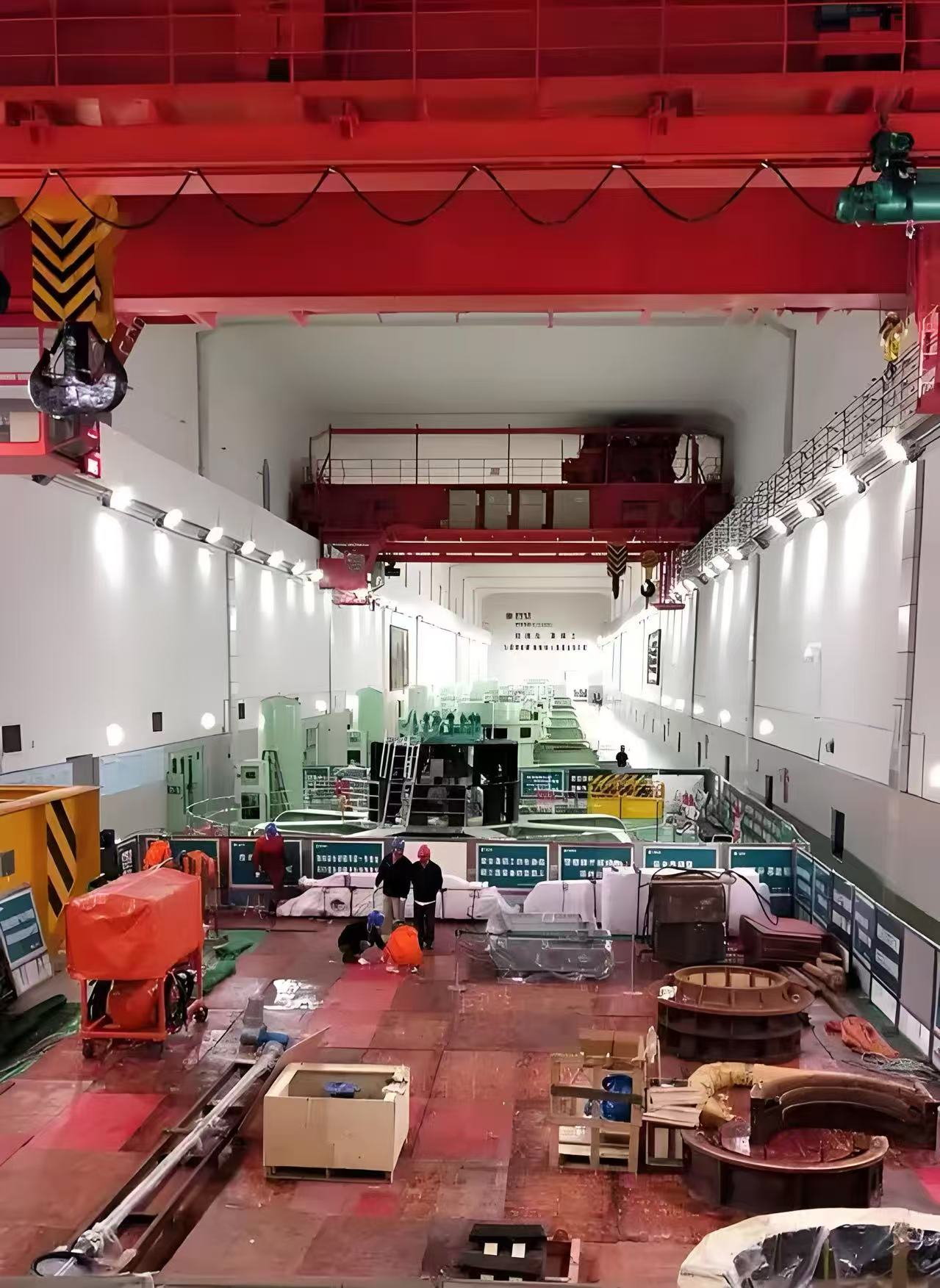
Introduction of Hydropower Station Bridge Cranes
1. Basic Definition
A bridge crane in a hydropower station is a core lifting device used for hoisting, installing, and maintaining large equipment within the power station, such as turbines, generators, transformers, and gates. It is typically characterized by its large lifting capacity, high precision, and strong stability. Key information includes:
Function: Handles the lifting, assembly, maintenance, and daily care of heavy equipment in the main plant of the hydropower station.
Types:
· Large Power Stations: Often use double-girder bridge cranes.
· Small Power Stations: May use single-girder bridge cranes.
Lifting Capacity: Usually ranges from 20 to 500 tons, with some large power stations reaching over 1000 tons.
2. Main Structural Components
Bridge (Main Girder and End Beams)
· Main Girder: Uses a double-girder structure (box girder or truss girder), primarily bearing the lifting load.
· End Beams: Connect the ends of the main girders and install the main travel mechanism.
Handling Trolley
· Hoisting Mechanism: Equipped with a main hook (for heavy lifting) and a secondary hook (for auxiliary lifting), including wire rope drums and brakes.
· Trolley Travel Mechanism: Drives the trolley to move laterally along the main girder, usually electrically powered.
Main Travel Mechanism
· Function: Drives the crane to move longitudinally along the track in the plant, including motors, reducers, wheel sets, and track cleaning devices.
Electrical Control System
· Drive Control: Uses a variable frequency speed control system to achieve precise positioning (error ≤2mm).
· Safety Protection: Includes overload limiters, limit switches, collision sensors, and emergency stop buttons.
Auxiliary Devices
· Operator Cabin: Features air conditioning and anti-vibration design to provide a comfortable working environment.
· Lighting System: Ensures proper lighting in the work area.
· Access Ladder: Facilitates the entry and exit of operators.
· Maintenance Platform: Facilitates maintenance and repairs.
3. Technical Features and Requirements
High Precision Positioning
· Uses variable frequency speed control + encoder feedback technology to ensure stable positioning during the lifting of precision components like turbine rotors.
Dual Hook Coordinated Operations
· The main hook and secondary hook can work together, achieving load balance through PLC control (e.g., flipping gates).
Special Environmental Adaptability
· Corrosion and Moisture Resistance: Electrical components have a protection rating of IP55, and steel structures are coated with heavy-duty anti-corrosion paint.
· Seismic Design: Meets the seismic intensity requirements of the power station location (e.g., 8 degrees).
Safety Redundancy Design
· Equipped with a dual braking system (mechanical + electrical), multiple limit protections, and real-time overload monitoring systems to ensure safe operation.
4. Key Technical Parameters Example
|
Item |
Parameter Range |
|
Rated Lifting Capacity |
Main Hook: 20~1000 tons, Secondary Hook: 5~100 tons |
|
Span |
10~30 meters (based on plant width) |
|
Lifting Height |
Main Hook: 10~40 meters, Secondary Hook: 12~50 meters |
|
Work Class |
A5~A7 (heavy or extra heavy) |
|
Operating Speed |
Main Car: 20~40 m/min, Trolley: 5~15 m/min |
5. Selection Points
Determine the rated load based on the maximum weight of a single piece of equipment (e.g., generator rotor).
The span must cover all areas requiring lifting within the main plant.
Reserve load margin for future unit expansion (typically a 20% safety factor).
6. Operation and Maintenance Management
Regular Inspections
· Check for wear on wire ropes, brake clearance, and track level (calibrated annually).
· Insulate electrical system tests (quarterly).
Special Operating Conditions
· Switch to "micro-motion mode" (speed ≤1 m/min) when lifting precision components.
· Conduct a comprehensive inspection of structural deformations and electrical safety after heavy rain or earthquakes.
Lifespan Management
· Main structure lifespan ≥30 years, critical components (such as wire ropes, brake pads) are replaced on a schedule.
Summary
Bridge cranes in hydropower stations are core equipment for construction and operation, with their reliability and performance directly impacting the efficiency of unit installation and the safety of the power station. Design considerations must include load capacity, precision control, and long-term durability to ensure stable operation under various conditions.


